Rendering volume aurorae and nebulae
Some notes on my trials and tribulations adding aurorae to Gaia Sky
A few weeks ago someone created an issue in the Gaia Sky Codeberg repository requesting the addition of aurorae to the Earth. They used as an example the aurora add-on in Cosmographia1, which, at the time, looked to me like it was using some kind of billboard particle system to generate the effect. I never thought it looked particularly good for an aurora; I thought Gaia Sky could do better. So I set on a quest to implement a better looking aurora object in Gaia Sky. This wee quest would involve implementing three very different approaches to aurora rendering over the span of a few weeks, plus more than half a dozen 3D volume nebulae.
In this post, I present the three different methods I implemented to render aurorae. But before anything, I need to take a small detour and talk about nebulae.
Li’l nebulae detour
If every story should start at the beginning and be told in full, I must first relate how this little quest took a little detour, at the beginning, to explore the rendering of volume nebulae. The OP mentioned in the Codeberg issue that he also gets requests to fly into nebulae during his tours, and Gaia Sky only contained billboards so far. Since Gaia Sky already had the necessary infrastructure to render ray-marched volumes using a screen quad in a post-processing effect, I decided that addressing this issue first made sense, as it seemed to require a much lower effort and friction.
Typically, volumes are rendered using an in-scene model (normally a box) that encapsulates the volume fully. The fragments that hit the model faces are sent to through the pipeline, and the volume ray-marching or ray-tracing is implemented in the respective fragment shader. In our approach, we’ll use a post-processing stage, which means that we create a full screen quad and we run a fragment shader for every pixel in our screen or window. The main challenges of this approach are:
- Ground the model in the scene world. Since we are essentially painting on an empty, flat canvas, we need to ground our 3D volume in our 3D world. This step is taken care of by carefully selecting the coordinate system and constructing the ray direction for each fragment and camera and object positions correctly.
- Interaction with the depth buffer. We need our volume to be occluded by objects closer to the camera, and the opaque portions of our volume need to occlude further away parts of the scene. To fix this, we pass in the current depth buffer as a texture so that we can sample it at every pixel. Additionally, we also pass in the current scene frame buffer so that we have full control over the blending of our volume with the rest of the scene.
To get started, I browsed through shadertoy in search for a good implementation of a ray-marched shader that I could use as a base for my nebulae. I found several, like the Dusty Nebula 4 by Duke, and the Supernova Remnant, also by Duke. This Duke guy seems to be the most prolific shadertoy author when it comes to large-scale dusty objects, and by a large margin. It’s not even close, so props to him and thank you very much for your work. All of his shaders seem to be licensed under CC-BY-NC-SA 3.0, which is perfect for modification and reuse in Gaia Sky.
So, taking some of these shaders as a baseline, I created new ones for the Cat’s Eye nebula, the Hourglass nebula, the Trifid nebula, the Butterfly nebula, and the Crab nebula, among others. You can see some of them here.
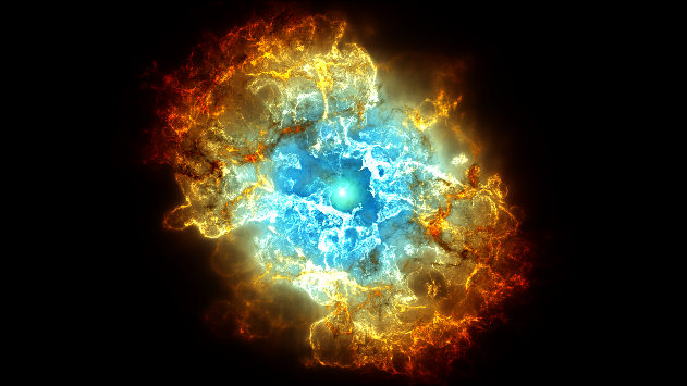
My implementation of the Crab nebula as a volume. See it live on Shadertoy.
Once the Shadertoy shaders were ready, I did a little more work on the post-processing ray-marching infrastructure to accommodate the new members. So far, I had only ever used it for the black holes. The final step was translating the shaders from Shadertoy to Gaia Sky. This was not too difficult, as they were already created with that step in mind.
Anatomy of a nebula shader
As we mentioned, currently the nebulae are implemented in the post-processor. This means that they are rendered in image space after the main rendering stage, which renders the geometry, has finished.Post-processors get as input data the current frame buffer, the depth buffer, and whatever additional textures are needed for the particular effect (such as one or more noise textures). Additionally, they get positions and orientations as uniforms or varyings computed in the vertex stage.
All nebula shaders have the same main parts:
Set up – here we prepare the data for the raymarching step. The ray direction, the camera position and the object position are all computed/fetched here. We also recover the depth for the current fragment from the depth buffer. The set-up is typically done in the
main()function. In the following code we have an example of how the set-up stage is done.Code: set-up example
#version 330 core

// Color buffer.
uniform sampler2D u_texture0;
// Depth buffer (log).
uniform sampler2D u_texture1;
// Position of our camera with respect to the object to render.
uniform vec3 u_pos;

// Texture coordinates.
in vec2 v_texCoords;
// Ray from camera to fragment.
in vec3 v_ray;

// Output color.
layout(location = 0) out vec4 fragColor;

void main() {
    // Ray direction.
    vec3 rayDir = normalize(v_ray);
    // Camera position.
    vec3 camPos = u_pos;
    // Position of object. We always put the position of the object at the origin.
    vec3 objPos = vec3(0.0, 0.0, 0.0);
    // Sample depth buffer.
    float depth = texture(u_texture1, v_texCoords).r;
    depth *= length(rayDir);
    // Color of pre-existing scene.
    vec3 col = texture(u_texture0, v_texCoords).rgb;

    // Here would go the call to ray-marching.

    // Finally, the blending would go here.
}
Ray marching – here is where the actual ray-marching happens. In ray marching, we shoot a ray for every pixel, divide it into samples, and gather information at every step. This information is usually the density and color of the medium we are rendering.
Intersection check – since we implement this in image space (we shoot a ray for each pixel in our window), we first need to check whether our ray intersects the bounding volume containing the object or not. In nebulae, this volume is typically a sphere. Simply enough, this is done with a straightforward ray-sphere intersection function, which returns the intersection near and far distances if there is an intersection at all, or nothing if the ray does not hit the sphere. The code below shows how to do the ray-sphere intersection.
Code: ray-sphere intersection example
bool RaySphereIntersect(vec3 org, vec3 dir, out float near, out float far) {
    float b = dot(dir, org);
    float c = dot(org, org) - 8.0;
    float delta = b * b - c;
    if (delta < 0.0)
        return false;
    float deltasqrt = sqrt(delta);
    near = -b - deltasqrt;
    far = -b + deltasqrt;
    return far > 0.0;
}
Main loop – here we loop over a maximum number of iterations and accumulate the density. Every cycle advances our position through the ray by a given step distance. The code below illustrates a rather typical main loop. The following code completes the
main()function to include the call to the main loop (raymarching()) and the alpha blending at the very bottom.Code: main loop example
#define ITERATIONS 50

vec4 raymarch(vec3 camPos, vec3 rayDir, vec3 objPos, float depth) {
    // Ray direction.
    vec3 rd = rayDir;
    // Ray origin.
    vec3 ro = camPos;

    // ld, td: local, total density
    // w: weighting factor
    float ld = 0.0, td = 0.0, w = 0.0;

    // t: length of the ray
    // d: distance function
    float d = 1.0, t = 0.0;

    const float h = 0.1;

    vec4 sum = vec4(0.0);

    float min_dist = 0.0, max_dist = 0.0;

    // If our ray intersects the sphere...
    if (RaySphereIntersect(ro, rd, min_dist, max_dist)) {
        t = min_dist * step(t, min_dist);

        // Raymarch loop
        for (int i = 0; i < ITERATIONS; i++) {
            vec3 pos = ro + t * rd;

            // Loop break conditions.
            // Here we check the current distance agains the depth and the
            // maximum distance.
            if (t > depth || t > max_dist) break;

            // Evaluate distance function.
            // The map function returns the density at a given position.
            float d = map(pos);

            // Point light calculations.
            vec3 ldst = vec3(0.0) - pos;

            // Here, the color of light depends on the distance from the center
            // of the object. Typically, this is more complicated than what's here.
            vec3 lightColor = mix(colorA, colorB, ldst);

            if (d < h) {
                // Compute local density.
                ld = h - d;

                // Compute weighting factor.
                w = (1.0 - td) * ld;

                // Accumulate density.
                td += w + 1.0 / 200.0;

                vec4 col = vec4(0.3, 0.3, 0.3, td);

                // Emission.
                sum += sum.a * vec4(sum.rgb, 0.0) * 0.2;

                // Uniform scale density.
                col.a *= 0.2;
                // Colour by alpha.
                col.rgb *= col.a;
                // Alpha blend in contribution.
                sum = sum + col * (1.0 - sum.a);
            }
            td += 1.0 / 90.0;

            // Optimize step size near the camera.
            t += max(d * 0.1 * max(min(length(ldst), length(ro)), 1.0), 0.01);
        }

        // Simple scattering.
        sum *= 1. / exp(ld * 0.2) * 0.4;
        sum = clamp(sum, 0.0, 1.0);
        sum.xyz = sum.xyz * sum.xyz * (3.0 - 2.0 * sum.xyz);
    }
    return vec4(sum.xyz, td);
}
Blending – finally, we have the blending. Most nebulae are blended using regular alpha blending, but implementing additive blending is trivial.
Code: alpha blending example
void main() {
    vec3 rayDir = normalize(v_ray);
    vec3 camPos = u_pos * 2.0e-7;
    vec3 objPos = vec3(0.0, 0.0, 0.0);
    float depth = texture(u_texture1, v_texCoords).r;
    depth *= length(rayDir);
    vec3 col = texture(u_texture0, v_texCoords).rgb;

    // Ray marching.
    vec4 rmcol = raymarch(camPos, rayDir, objPos, depth);

    // Alpha blending.
    fragColor = vec4(col * (1.0 - rmcol.a) + rmcol.rgb * rmcol.a, 1.0);
}
This covers the basics of our nebulae shaders. The video below shows some of the nebulae that I have adapted for Gaia Sky and that will be available in the NGC2000 catalog when the next version is out, soon™.
Six of the new nebulae implemented in Gaia Sky.
Now, back to the aurora.
Approaching aurora rendering
Aurorae are natural light displays caused by interactions between charged particles from the Sun (solar wind) and the Earth’s magnetosphere and atmosphere. At the poles, magnetic field lines converge and funnel these particles into the upper atmosphere (thermosphere), where they collide with oxygen and nitrogen molecules. The collisions excite the molecules, causing electrons to jump to higher energy states. The excited atoms are unstable, so as the electrons return to their normal states, they release packets of energy in the form of photons. The color (frequency) of these photons depends on the type of gas and altitude: green from oxygen (~100-150 km), red from oxygen higher up, where lower density causes slower de-excitation (~200+ km), and blue or purple from nitrogen. The shifting, curtain-like shapes result from changes in the solar wind and Earth’s magnetic field.
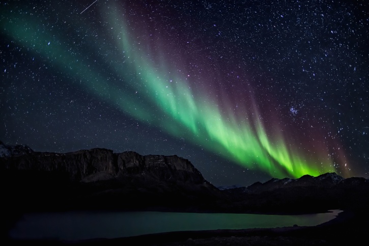
A picture of an aurora borealis in Greenland. The green, red and blue colors can be seen in different parts of the curtains. Photo by Visit Greenland on Pixnio, CC0.
Aurorare are, then, purely volumetric and perfectly emissive phenomena. This fact strongly points to a volume ray-caster being the best method for rendering aurorare, but implementing volume rendering shaders is hard, so I explored some alternative options first. I have very creatively labeled them 1, 2 and 3.
1. Mesh w/ custom shader
I like to simplify problems to their very basics. Even though aurora curtains have volume (width), their extent is limited when compared to their height or their footprint length. So, obviously, my first thought was to implement aurorae as a curved mesh with a special shader to render the curtain elements. I knew it wouldn’t look super good, but maybe it was good enough.
I set up the infrastructure and created the object. At first, I used an uncapped cylinder mesh. The faces are unculled, since they need to be visible from both sides. Once the mesh was in place, I created the fragment shader which would render the actual emissive elements. This shader is available on Shadertoy: Base Aurora Shader.
I loaded the shader and applied it to the mesh. The results were… underwhelming. The shader itself is ok, but when applied to the flat surface of the cylinder, it just does not cut it. When the camera moves the effect is totally shattered and you can tell right away that this is a flat object.
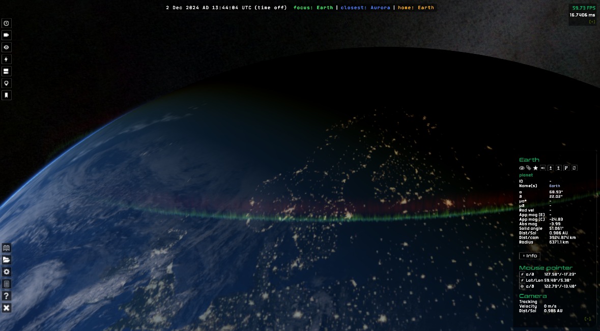
The aurora shader on a cylindrical mesh, seen from afar.
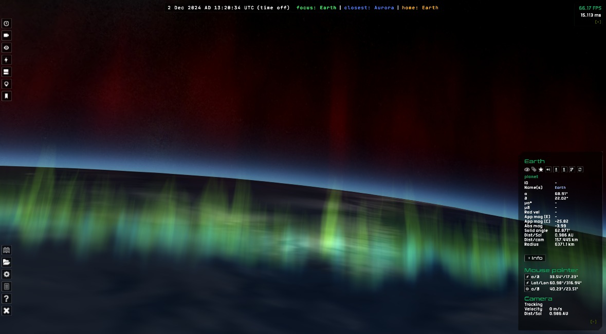
A close-up. Meh.
It was clear to me that this wasn’t good enough. So I went browsing on shadertoy again.
2. Isolated noise aurora
I’ll start by saying that this second effort went nowhere, but had the pleasant side effect of having implemented the true in-scene, bounding box-based volume infrastructure.
The base idea was to adapt a pre-existing ray-marching shader to be rendered as a volume in Gaia Sky. The shader in question is here.
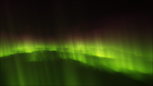
The isolated aurora shader ray-marches an aurora using fractal brownian motion noise as footprints. Looks good in shadertoy, not so much in Gaia Sky. See it live on Shadertoy.
That shader contains some code to to intersect the ray with an axis-aligned bounding box (AABB), so naturally I implemented the necessary infrastructure to be able to ship external volume rendering shaders on bounding meshes. And it kind of worked, but I could never make it behave exactly the way I wanted. I had several problems with the integration in Gaia Sky, so instead of spending lots of time and effort into solving them only to end up with a half-assed, bad-looking aurora, I decided to try the next approach.
3. True volume aurora
This is the good one. It is based on Lawlor and Genetti’s 2011 paper “Interactive Volume Rendering Aurora on the GPU”2. Key innovations include a height-based aurora model, a GPU-friendly atmosphere model, efficient ray marching with distance fields, and interactive frame rates (20–80 FPS). The aurora footprints are initially represented as splines, which are then fed into a stem-like fluid simulator to generate the true footprint textures. Then, they sample the rays and stretch the footprints in the vertical direction using a physically-based vertical electron deposition function. They also accelerate the ray-marching step using a 2D signed distance field (SDF) texture generated from the footprint.
I implemented all of this and the results were quite good. I drew the footprints myself using Gimp. I use cubemaps for the footprints and the signed distance function texture, as they eliminate the artifacts at the poles typical of regular UV mapping on spheres. The aurora volume itself is modeled with a flipped sphere that wraps around the Earth. I generate it programmatically.
I generated the SDF textures with sdfer, a small CLI utility that generates distance fields from raster images.

Left: the footprint texture, created with Gimp. Center: the signed distance function texture. Right: the final render.
By far, the largest problem I faced was in the UV coordinate mapping. In order to sample the 2D textures from the 3D samples in the ray marching steps, I implemented a projection function that maps 3D points to 2D UV coordinates.
vec2 uv(vec3 p, vec3 rayDir, vec3 camPos) {
    p = normalize(p);
    return vec2(0.5 - atan(-p.z, -p.x) / (PI2), asin(-p.y) / PI + 0.5);
}
However, when the camera was inside the volume, this gave me mirrored ghosting aurorae in their opposite direction relative to the camera. I struggled to solve this issue for a while, until I realized that I just had to enforce that the sampling point had to be on the right side of the ray:
vec2 uv(vec3 p, vec3 rayDir, vec3 camPos) {
    if (dot(rayDir, p) > 0.000) {
        // Ok.
        p = normalize(p);
        return vec2(0.5 - atan(-p.z, -p.x) / (PI2), asin(-p.y) / PI + 0.5);
    } else {
        // Invalid result.
        return vec2(5.0, 5.0);
    }
}
This solved the artifacts. I then implemented some additional suggestions by O. Lawlor (the paper’s author), and I got it to a state where I really liked it. See the video below:
The final volume aurora in Gaia Sky.
Future work
A few things can be improved in the current aurora:
- Render the aurorae to an off-screen buffer. This would unlock a series of benefits:
- Render at lower resolution to increase performance.
- Apply blur and glow to mitigate jittering artificts.
- Full control over blending with scene.
- Proper color modeling. The base and high colors are now passed in from a JSON descriptor file. This could be improved by adopting a physical model of the upper atmosphere and generating the colors accordingly.
Conclusion
In this post, I have shown how the new volume nebulae and aurorae in Gaia Sky came about. I have given some implementation details, and discussed their pros and cons. In the end, I think the time spent on this was well spent, as the results were quite satisfactory.
SPICE-Enhanced Comosgraphia Mission Visualization Tool, NAIF: https://naif.jpl.nasa.gov/naif/cosmographia.html ↩︎
Interactive Volume Rendering Aurora on the GPU, Journal of WSCG: https://www.researchgate.net/publication/220200705_Interactive_Volume_Rendering_Aurora_on_the_GPU ↩︎