Looking for new projects to sharpen my Rust skills, I came across a Reddit post where someone mentioned CHIP-8. CHIP-8 is an interpreted low-level programming language and virtual machine specification that is very commonly used as a “Hello world!” project of sorts for people to get their feet wet with emulator programming. It is simple enough to be able to implement a fully-featured emulator in a couple of sessions, but it has all the key parts of a real machine, to the point that are many projects that implement CHIP-8 directly in hardware.
I have since implemented my own CHIP-8 emulator in Rust (see repository here) with support for sound, display scaling, configurable colors, and more. But this text is not about it (I’ll write about my implementation in a future post). Today I want to fully describe the CHIP-8 machine, because I had fun implementing it, and I like it so much that I want to have it here for my future reference. In this guide, every instruction is accompanied with a small pseudo-code block to help understand the interpreter’s intended behavior to the more technically inclined reader.
The CHIP-8 specification document I used as reference to implement my version is Cowgod’s Chip-8 technical reference1, and I also had a look at a guide by Tobias V. Langhoff.2
Some history
CHIP-8 was initially designed and developed by Joseph Weisbecker in 1977 in order to enable easy game development for the COSMAC VIP kit computer. The instruction set is quite simple, based on hexadecimal codes, and it is suited for machines with very scarce memory and computing power. It has enjoyed different levels of success over the decades, and today it has a community of people who write games and other programs for it. It is considered one of the easiest machines to emulate, and mostly everyone who is interested in emulator development starts with CHIP-8.
Bird’s eye view
The programs (or ROMS) are strictly hexadecimal based. This means that the bytes themselves are written directly into a file in binary form, and are readable only through a Hex editor or any other type of utility that allows for binary inspection. The programs are not, then, written in text file as it is commonly done with more common programming languages such as ASM, C or Rust.
The CHIP-8 machine has 4 kB (4096 bytes) of memory, 16 general purpose 8-bit registers plus five special ones (index –I–, program counter –PC–, stack pointer –SP–, and delay and sound timers –DT and ST–), it relies on a simple keyboard with a 4x4 key layout for user input, it has a 64x32-pixel monochrome display (pixels can either be on or off), it has a stack of 16-bit values and it defines two timers to access times: the delay timer and the sound timer. The latter is used to sound the buzzer (beeeeep!).
Here are the main components of CHIP-8, summarized and itemized:
- RAM memory space: 4 kB (4096 B)
- 16 general purpose 8-bit registers
- The delay timer
DTregister (8-bit) - The sound timer
STregister (8-bit) - The index register
I(16-bit), used to store memory addresses - The program counter
PC, another pseudo-register (16-bit) that points to the address in memory of the current instruction - The stack pointer
SP, a pseudo-register (8 or 16-bit, depending on the size of your stack) that points to the top of the stack - The stack, a LIFO array of 16-bit values used for subroutines
- The keyboard, which contains 16 keys used as input
- The buzzer, used to spit out beep sounds
In the following sections I describe each of this components in enough detail that you should be able to write a full CHIP-8 emulator with just the information conveyed here.
Memory
CHIP-8 has 4 kB (4096 B) of RAM. It is indexed from location 0x000 to 0xFFF.
- The addresses from
0x000to0x200are reserved for the system. Nowadays, this area contains fonts for the 16 Hex characters. Originally, this space contained the interpreter code. - The addresses from
0x200up are where the user programs are located. Most programs start at0x200, and that’s where your emulator should put the code read from ROM files. User programs intended for the ETI 660 computer begin at0x600. By convention, all instructions start at even addresses.
Here is a shitty diagram of the memory layout:
 ADDRESS                                         CONTENT
 ~~~~~~~                                         ~~~~~~~

   0x000  --------------------------------  <--  Start of RAM
          |                              |
          |  Interpreter code, fonts     |
          |                              |
   0x200  --------------------------------  <--  Start of user programs
          |                              |
          |                              |
          |      User programs and       |
          |        data go here          |
          |                              |
          |                              |
   0x600  ................................  <--  Start of user programs (ETI 660)
          |                              |
          |                              |
          |                              |
          |                              |
          |      User programs and       |
          |        data go here          |
          |                              |
          |                              |
          |                              |
          |                              |
   0xFFF  --------------------------------  <--  End of RAM
Some programs expect fonts to be available starting at the 0x000 address. My implementation loads the following bytes at that address, containing the fonts for the Hex decimals from 0 to F:
    0xF0, 0x90, 0x90, 0x90, 0xF0, // 0
    0x20, 0x60, 0x20, 0x20, 0x70, // 1
    0xF0, 0x10, 0xF0, 0x80, 0xF0, // 2
    0xF0, 0x10, 0xF0, 0x10, 0xF0, // 3
    0x90, 0x90, 0xF0, 0x10, 0x10, // 4
    0xF0, 0x80, 0xF0, 0x10, 0xF0, // 5
    0xF0, 0x80, 0xF0, 0x90, 0xF0, // 6
    0xF0, 0x10, 0x20, 0x40, 0x40, // 7
    0xF0, 0x90, 0xF0, 0x90, 0xF0, // 8
    0xF0, 0x90, 0xF0, 0x10, 0xF0, // 9
    0xF0, 0x90, 0xF0, 0x90, 0x90, // A
    0xE0, 0x90, 0xE0, 0x90, 0xE0, // B
    0xF0, 0x80, 0x80, 0x80, 0xF0, // C
    0xE0, 0x90, 0x90, 0x90, 0xE0, // D
    0xF0, 0x80, 0xF0, 0x80, 0xF0, // E
    0xF0, 0x80, 0xF0, 0x80, 0x80, // F
Registers
CHIP-6 programs can use 16 general purpose 8-bit registers which can be accessed and manipulated directly with some of the instructions.
The 16 registers’ names are of the format VX, where X is a hexadecimal digit from 0 to F, so the registers are V0 to VF. Additionally, VF is used to store the carry (additions) and borrow (subtractions) flags, and should not be used by the programs directly.
CHIP-8 also has two 8-bit special purpose registers, named delay timer DT and sound timer ST. See the Timers section for more on them.
The program counter PC is 16-bit and contains the memory address of the current instruction.
The stack pointer SP is either 8 or 16-bit (depending on the size of your stack), and points to the top of the stack.
Finally, we have the index register I, which is a 16-bit register typically used to store memory addresses.
Stack
The stack is a LIFO array of 16-bit values used mainly to store addresses the interpreter should return to after subroutines have finished. I think the CHIP-8 specification allows for 16 levels of nested subroutine calls, so your stack should at least contain 16 places. In that case, an 8-bit SP is enough.
Input
The original CHIP-8 implementations used a keypad with 16 keys, labeled with the hexadecimals 0 to F:
123C
456D
789E
A0BF
Of course, nowadays nobody expects anyone to have one of these physical keypads, so emulators typically map it to the keyboard. Usually, the map is done like this:
1234
QWER
ASDF
ZXCV
Display
The display is a monochrome setup with a resolution of 64x32 pixels. The pixel at [0, 0] corresponds to the top-left corner, and the pixel [63, 31] corresponds to the bottom-right.
  [0,0]                      [63,0]
  ┌───────────────────────────────┐
  │                               │
  │                               │
  │         64x32 DISPLAY         │
  │                               │
  │                               │
  └───────────────────────────────┘
  [0,31]                    [63,31]
The graphics are drawn to the screen using 8x15 sprites which reside in memory as 15 consecutive bytes. Each of the bytes is interpreted as a row of bits that encode the on/off state of each of the pixels. We could draw a window with something this:
  HEX          BINARY          IMAGE

  0XFF        11111111        ■■■■■■■■
  0X99        10011001        ■  ■■  ■
  0X99        10011001        ■  ■■  ■
  0XFF   =>   11111111   =>   ■■■■■■■■
  0X99        10011001        ■  ■■  ■
  0X99        10011001        ■  ■■  ■
  0XFF        11111111        ■■■■■■■■
The figure below shows the display after running this test ROM with my CHIP-8 emulator.
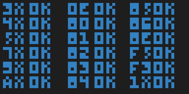
CHIP-8 display with test ROM
Timers
There are two special 8-bit registers used as timers, the DT and the ST.
The delay timer DT is automatically decremented with a frequency of 60 Hz (60 times per second) whenever its value is greater than zero (> 0). That’s all it does. Its value can be read into a registry and written with FX07 and FX15 respectively.
The sound timer ST is also automatically decremented with a frequency of 60 Hz when its value is greater than zero. Additionally, when this happens (ST > 0) the system sounds the buzzer to produce a beep. So, for example, if you want your program to sound the buzzer for one second, you need to write 0x3C to ST. It can be set with FX18 but it can’t be read.
Instruction set
This section describes each of the 36 instructions available in CHIP-8. It is by far the longest section, but most of the instructions are actually quite simple. By convention, all instructions start at even addresses.
Each instruction is 2 bytes long and are stored with the most-significant byte first. Instructions have the one of the format CXYN, CXNN or CNNN, where each of the characters is 4 bits. C is the code or group. X and Y are typically used to refer to register numbers. N, NN and NNN are 4, 8 and 12-bit literal numbers used to set values or for further instruction identification within a group (since 4 bits would only allow for 16 instructions). Instructions are decoded by splitting them into chunks and grouping them accordingly.
In the descriptions below I will use pseudo-code blocks to illustrate exactly the actions that the interpreter must take to execute the instruction.
CLS — 00E0
Clear the display by setting all pixels to ‘off’.
RET — 00EE
Return from a subroutine. Pops the value at the top of the stack (indicated by the stack pointer SP) and puts it in PC.
PC := stack[SP]
JMP — 1NNN
Jump to the address in NNN. Sets the PC to NNN.
PC := NNN
CALL NNN — 2NNN
Call the subroutine at address NNN. It increments SP, puts the current PC at the top of the stack and sets PC to the address NNN.
SP += 1
stack[SP] := PC
PC := NNN
SE VX, NN — 3XNN
Skip the next instruction if VX == NN. Compare the value of register VX with NN and if they are equal, increment PC by two.
if VX == NN:
    PC += 2
SNE VX, NN — 4XNN
Skip the next instruction if VX != NN. Compare the value of register VX with NN and if they are not equal, increment PC by two.
if VX != NN:
    PC += 2
SE VX, VY — 5XY0
Skip the next instruction if VX == VY. Compare the value of register VX with the value of VY and if they are equal, increment PC by two.
if VX == VY:
    PC += 2
LD VX, NN — 6XNN
Load the value NN into the register VX.
VX := NN
ADD VX, NN — 7XNN
Add the value NN to the value of register VX and store the result in VX.
VX := VX + NN
LD VX, VY — 8XY0
Put the value of register VY into VX.
VX := VY
OR VX, VY — 8XY1
Perform a bitwise OR between the values of VX and VY and store the result in VX.
VX := VX | VY
AND VX, VY — 8XY2
Perform a bitwise AND between the values of VX and VY and store the result in VX.
VX := VX & VY
XOR VX, VY — 8XY3
Perform a bitwise XOR between the values of VX and VY and store the result in VX.
VX := VX ^ VY
ADD VX, VY — 8XY4
Add the values of VX and VY and store the result in VX. Put the carry bit in VF (if there is overflow, set VF to 1, otherwise 0).
if VX + VY > 0xFF:
    VF := 1
else:
    VF := 0

VX := VX + VY
SUB VX, VY — 8XY5
Subtract the value of VY from VX and store the result in VX. Put the borrow in VF (if there is borrow, VX > VY, set VF to 1, otherwise 0).
if VX > VY:
    VF := 1
else:
    VF := 0

VX := VX - VY
SHR VX {, VY} — 8XY6
Shift right, or divide VX by two. Store the least significant bit of VX in VF, and then divide VX and store its value in VX
VF := VX & 0x01
VX := VX / 2
SUBN VX, VY — 8XY7
Subtract the value of VY from VX and store the result in VX. Set VF to 1 if there is no borrow, to 0 otherwise.
if VY > VX:
    VF := 1
else:
    VF := 0

VX := VY - VX
SHL VX {, VY} — 8XYE
Shift left, or multiply VX by two. Store the most significant bit of VX in VF, and then multiply VX and store its value in VX
VF := VX & 0x80
VX := VX * 2
SNE VX, VY — 9XY0
Skip the next instruction if the values of VX and VY are not equal.
if VX != VY:
    PC := PC + 2
LD I, NNN — ANNN
Set the value of I to the address NNN.
I := NNN
JMP V0, NNN — BNNN
Jump to the location NNN + V0.
PC := V0 + NNN
RND VX, NN – CXNN
Generate a random byte (from 0 to 255), do a bitwise AND with NN and store the result to VX.
VX := random() & NN
DRW VX, VY, N — DXYN
The draw instruction. This is arguably the most involved operation. The n-byte sprite starting at the address I is drawn to the display at the coordinates [VX, VY]. Then, set VF to 1 if there has been a collision (a display bit was changed from 1 to 0).
The interpreter must read N bytes from the I address in memory. These bytes are interpreted as a sprite and drawn at the display coordinates [VX, VY]. The bits are set using an XOR with the current display state.
xcoord := VX % DISPLAY_WIDTH
ycoord := VY % DISPLAY_WIDTH

// iterate over bytes
for row in 0..N:
    bits := RAM[I + row]
    cy := (ycoord + row) % DISPLAY_HEIGHT

    // iterate over bits
    for col in 0..8:
        cx := (xcoord + col) % DISPLAY_WIDTH
        curr_col := DISPLAY[cx, cy]
        // get value of bit
        col := bits & (0x01 << 7 - col)
        // do XOR
        if col > 0:
            if curr_col > 0:
                DISPLAY[cx, cy] := 0
                VF = 1
            else:
                DISPLAY[cx, cy] := 1

        if cx == DISPLAY_WIDTH - 1:
            break

    if cy == DISPLAY_HEIGTH - 1:
        break

update_display()
Phew, that was long. You can implement it differently, but in this pseudo-code chunk all the necessary steps are explicitly laid out. Basically, loop over the N bytes starting at memory address I. Then for each bit in each byte, do the XOR with the current display, taking care of setting VF to 1 if there was a collision.
SKP VX — EX9E
Skip the next instruction if the key with the value of VX is currently pressed. Basically, increase PC by two if the key corresponding to the value in VX is pressed.
if keys[VX] == 1:
    PC := PC + 2
The snippet assumes that the vector keys[] has a length of 16, and contains 1 if the key corresponding to the index is pressed, 0 otherwise.
SKNP VX — EXA1
Skip the next instruction if the key with the value of VX is currently not pressed. Basically, increase PC by two if the key corresponding to the value in VX is not pressed.
if keys[VX] == 0:
    PC := PC + 2
The snippet assumes that the vector keys[] has a length of 16, and contains 1 if the key corresponding to the index is pressed, 0 otherwise.
LD VX, DT — FX07
Read the delay timer register value into VX.
VX := DT
LD VX, K — FX0A
Wait for a key press, and then store the value of the key to VX.
K := wait_input()
VX := K
LD DT, VX — FX15
Load the value of VX into the delay timer DT.
DT := VX
LD ST, VX — FX18
Load the value of VX into the sound time ST.
ST := VX
ADD I, VX — FX1E
Add the values of I and VX, and store the result in I.
I := I + VX
LD F, VX — FX29
Set the location of the sprite for the digit VX to I. The font sprites start at address 0x000, and contain the hexadecimal digits from 1..F. Each font has a length of 0x05 bytes. The memory address for the value in VX is put in I. See the display section.
I := VX * 0x05
LD B, VX — FX33
Store the binary-coded decimal in VX and put it in three consecutive memory slots starting at I.
VX is a byte, so it is in 0…255. The interpreter takes the value in VX (for example the decimal value 174, or 0xAE in hex), converts it into a decimal and separates the hundreds, the tens and the ones (1, 7 and 4 respectively). Then, it stores them in three memory locations starting at I (1 to I, 7 to I+1 and 4 to I+2).
// get hundreds, tens and ones
h := VX / 100
t := (VX - h * 100) / 10
o := VX - h * 100 - t * 10

// store to memory
RAM[I] := h
RAM[I + 1] := t
RAM[I + 2] := o
LD [I], VX — FX55
Store registers from V0 to VX in the main memory, starting at location I. Note that X is the number of the register, so we can use it in the loop. In the following pseudo-code, V[i] allows for indexed register access, so that VX == V[X].
for reg in 0..X:
   RAM[I + reg] := V[reg]
LD VX, [I] — FX65
Load the memory data starting at address I into the registers V0 to VX.
for reg in 0..X:
   V[reg] := RAM[I + reg]
Conclusion
We have seen a complete specification of CHIP-8, from the memory layout to the registers, the display and finally the instruction set. You can find loads of sites with ROMS available to download and test your CHIP-8 emulator. Additionally, there are many extensions and variations like the CHIP-8X, the CHIP-8X or the S-CHIP (also called Super-Chip). These add different features like new instructions or additional display modes. They are a bit more complex, but also very fun to implement and play around.
Cowgod’s Chip-8 technical reference: http://devernay.free.fr/hacks/chip8/C8TECH10.HTM ↩︎
Guide to making a CHIP-8 emulator: https://tobiasvl.github.io/blog/write-a-chip-8-emulator/ ↩︎